Proportion-Air Case Study
A Little Background on Fuel Pump Testing
Fuel pump manufacturers must spend time and energy testing fuel pumps to verify the required flow (at the pressures stated in their specification document) is achieved consistently. Fuel pump testing to verify various flows requires the ability to simulate many different pressures accurately. One way this is accomplished is by electronically controlling the back pressure from these pumps and then measuring the flow rate.
The Situation
One vehicle fuel pump manufacturer approached Proportion-Air with a desire to build a fuel pump test stand that could be used for testing fuel pumps of all sizes. There was a wide range of pressures and flows that would need to be simulated.
The Solution
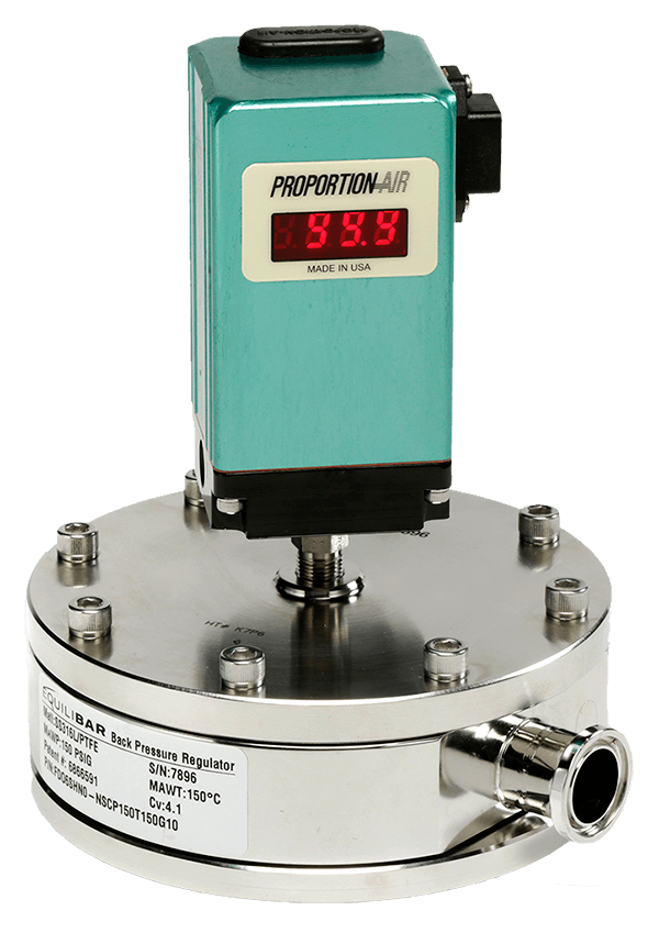
Proportion-Air offered a dual-loop electronically controlled back pressure regulator that satisfied their requirements and would be compatible with the test fluid, which was Stoddard solvent. A closed-loop proportional control QB2S/Equilibar/DST (DST Transducer not pictured) solution was provided. Then the assembly was installed in their new test fixture.
The Test
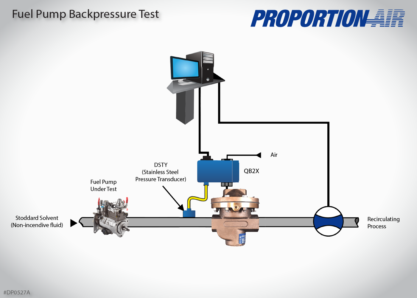
The back pressure regulator was plumbed downstream of the fuel pump during testing. The pump under test was turned on. At the same time, a command signal scaled to the back pressure for control went to the QB2s.
The QB2s pressurized the dome of the back pressure regulator to the pressure level required. The back pressure regulator remained closed until pump pressure exceeded dome pressure on the regulator. Excess Stoddard solvent was vented through the outlet port of the back pressure regulator and was measured by an electronic liquid flow meter. The signal from the flow meter was taken back to the customer’s Programmable Logic Controller (PLC) to display and record flow.
Fuel Pump
The Results
Because the QB2S is a closed-loop pressure controller (the DST external pressure transducer was plumbed between the pump output and the back pressure regulator input), working pressure of the pump can be monitored at all times through pin 5 of the QB2’s main electrical connector.
The flow signal from the electronic flow transducer and the pressure signal from the DST were the necessary signals the customer needed to print a flow-to-pressure chart for each pump.
A summary of benefits for the customer:
- One test fixture for all pumps replaced multiple test fixtures.
- The PLC-controlled electronic pressure regulator assembly eliminated the need for an operator to manually adjust a regulator for test set ups.
- The monitor signal of the QB2 assembly and the signal output of the electronic flow transducer allowed them to generate a flow-to-pressure chart with real data, eliminating the possibility of human recording error.
Only looking for a replacement product? Please use this form