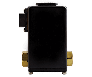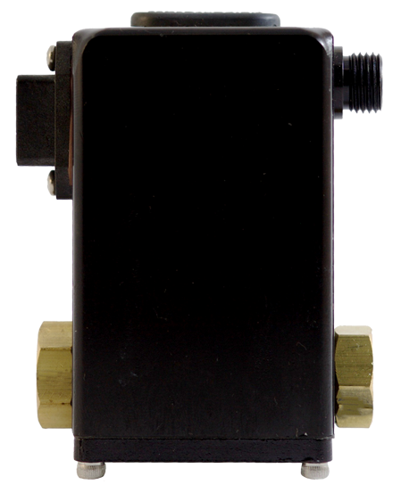
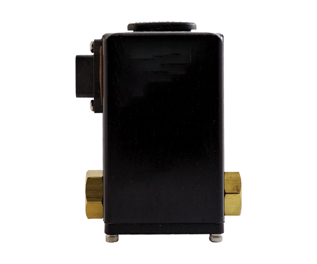
QBT Series
For all new applications, please see the QBX Model. The QBT model will be retired soon.
Why is the QBT Series listed as a legacy product? Both the QBT and BB series have been redesigned into a modern product that is more versatile and more efficient to manufacture with improved specifications – the QBX.
What other products are considered “Legacy Products”? Please check here
0.2%
Accuracy ±
Accuracy ±
0.02
Repeatability ±
Repeatability ±
1.2
Max Flow (SCFM)
Max Flow (SCFM)
175
Max P2 (PSI)
Max P2 (PSI)
- Technical Specs
- Downloads & Links
Technical Specs
| Pressure Range | Vacuum thru 175 PSI (12 Bar) |
| Accuracy | ±0.2% F.S. |
| Repeatability | ±0.02% F.S. |
| Max Flow | 1.2 SCFM (34 LPM) |
| Port Size | 1/8″ NPT (BSPP Available) |
| Durability | Immune to shock & vibration (up to 20 Gs) |
| Operating Temps | 32-158°F (0-70°C) |
| Filtration | 40 Micron |
Links
Downloads
File Request Form:: Use this form to request a file other than a standard QBT .STEP file
Submit the form below to download standard QBT .STEP files